Building a screen printing press – Part 6
The Screen Clamping System
In screen printing, we first produce a screen, which consists of a mesh stretched tightly over a frame. We then coat this screen with light sensitive emulsion, and use an ultra-violet light source to burn an image into the emulsion. After washing out the image, we are left with a stencil with the transparent parts held together by a mesh.
The screen must be mounted securely and positioned over the workpiece. To mount the screen, we use a clamping mechanism, and the process of positioning the screen is called registration.

The way the screen is clamped can have a significant effect on ease of registration, and often consists simply of a pair of thumb screws. For example, consider the set of hinged clamps pictured here. When tightening the individual screws, it is easy for the frame to shift under the mounting points.

While researching this, we found several positive comments describing a method where the frame is clamped by a single horizontal bar controlled by two screw knobs. This is the approach we adopted here. This way, the screws do not directly interact with the frame, and the frame does not shift while being clamped.
Building the screen clamp
To make one of these, we will need more of the same types of material we used previously, and also a 24x24mm square aluminum tubing. The other material used is our 10x20mm rectangular aluminum section for the bar, some 22x22mm equal angle (90 degree) lengths, and a couple of long 5mm screw knobs that we will manufacture ourselves as per instructions in the previous post.
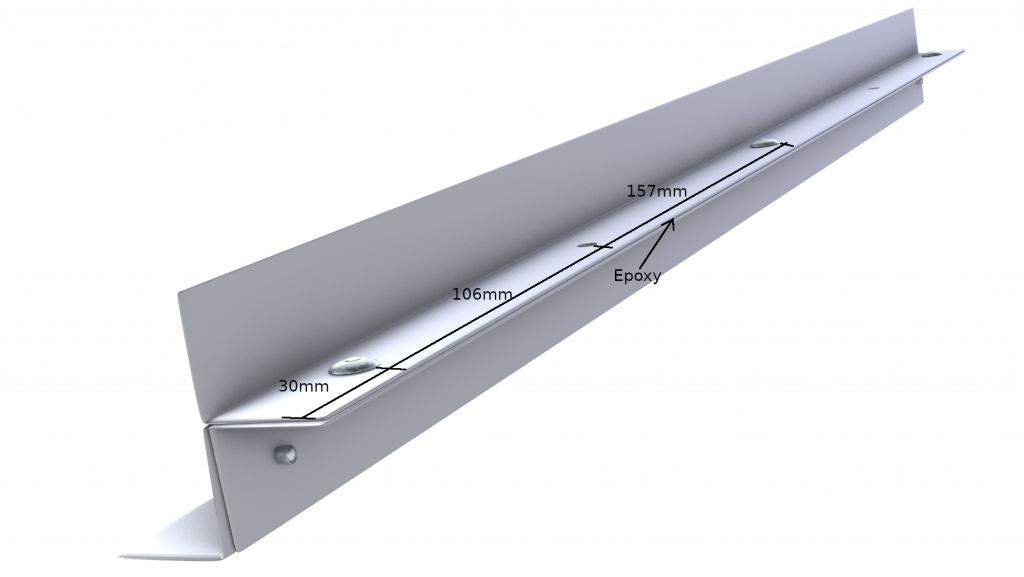
We use three equal angle sections arranged as shown. Notice how the arrangement forms a shelf for the screen to mount at the front, and the two rear sections come together in an arrangement we will use for attachment.
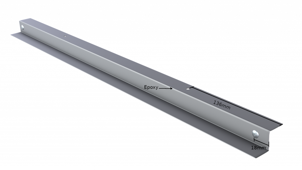
We connect the two bottom sections using just two rivets (18mm from the short edge) and some epoxy glue. We drill two 5mm holes in the rear bottom section, 136mm from either end.
The two rear sections fit together as one might expect, and are again joined together using epoxy glue and three rivets. We also drill two matching 5mm holes in the other rear section, 136mm from the short end. It is rather important that these 5mm holes match precisely with those on the lower section, and it may be a good idea to drill the holes through both upper and lower sections at the same time.
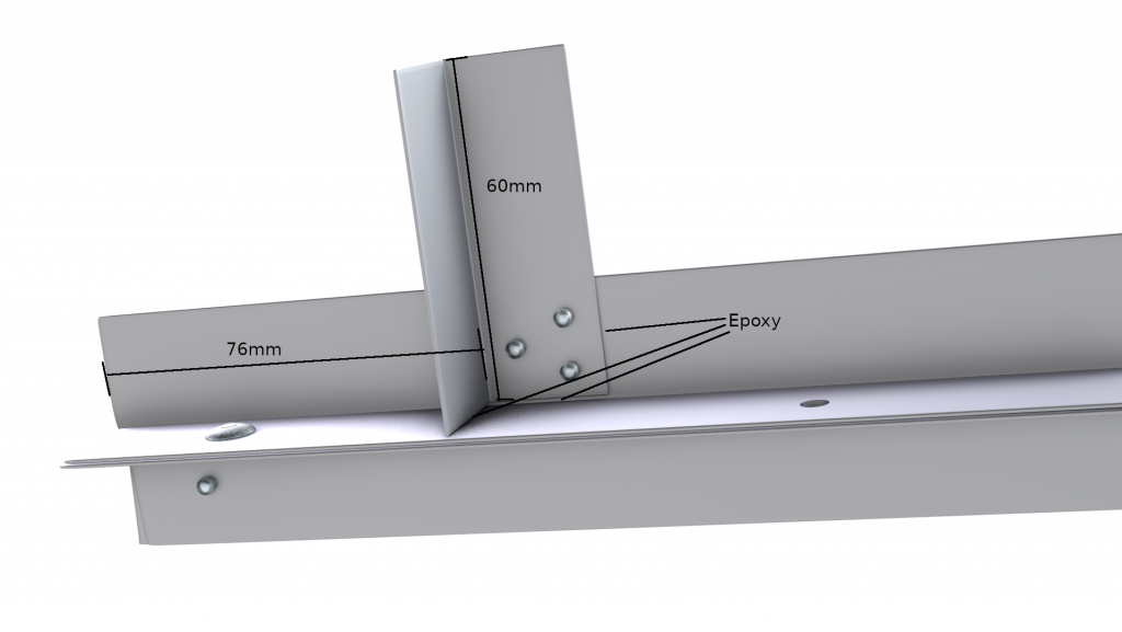
Having connected all three sections, we need two shorter 60mm equal angle sections of the same material, which we will use to make two short pillars. Again, we use epoxy and rivets to join the pieces. We also use epoxy at the “base” of this pillar to secure the section properly.
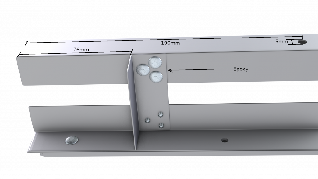
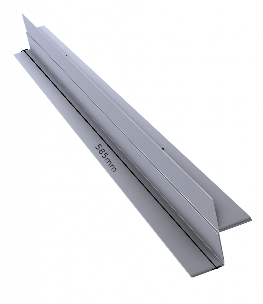
After the two pillars are attached, we can use these to fasten the top 585x24x24mm square aluminum tubing section, which we will use to house our screw knobs. We use rivets and epoxy glue again, a process by now becoming quite familiar. We drill a perpendicular 5mm hole straight through the square tubing, 190mm from each of the short edges. These holes will house the long 5mm screw knobs.
Under and above the 24mm square aluminum tubing, we have nuts secured with epoxy glue to the square section, allowing each screw to be turned up or down, using the knob.
The clamping unit is driven by two long 5mm screw knobs, each of which ends in a nut. This nut is inserted from the side into a 275mm length of 10x20mm rectangular aluminum tubing, and locked into place with loctite/superglue, such that it holds the aluminum clamping bar in place and the screws are fixed.
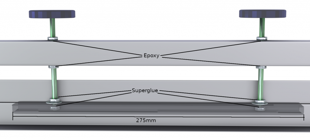
Above the bar is a washer and another bolt, which is also locked in place with superglue. There is some play allowed between the nut on top of the clamping bar and the one inside the bar, such that the inner nut rests against the bottom of the clamping bar when the nut from above applies pressure to the top of the bar.
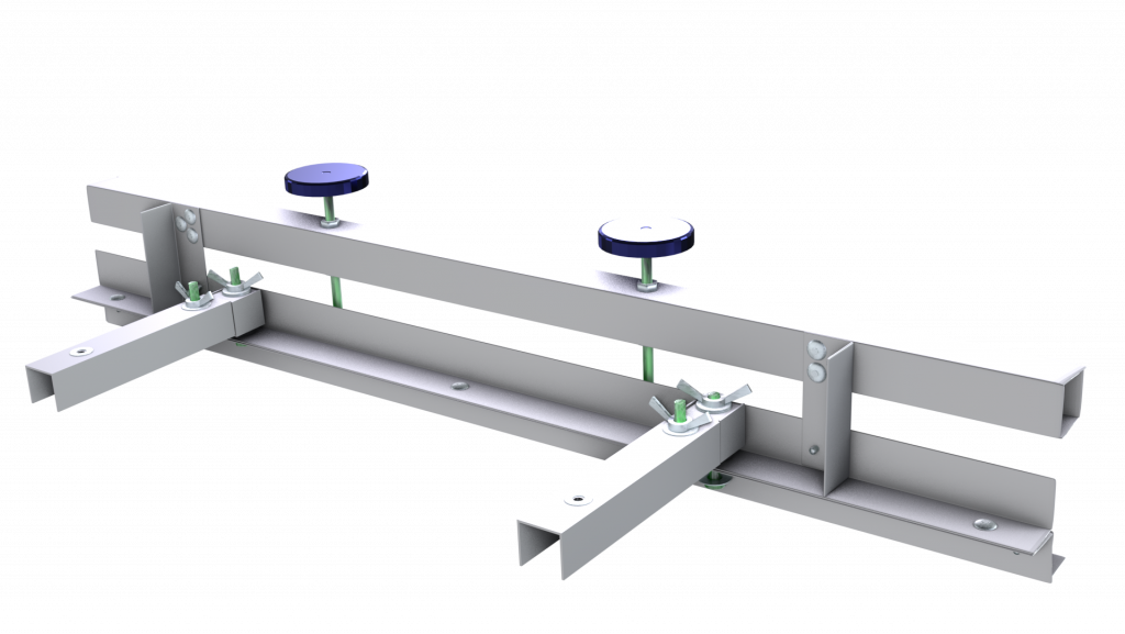
Using the Screen Clamping Unit

The screen clamping unit consists of the screen clamp discussed here, as well as a set of extension units we introduced in the previous post. The extension units fasten to the back of the screen clamp, and locked into place during screen registration. A screen clamped into the unit and registered may be removed as a whole, using the mounting knobs at the back, and replaced when needed.
One screen clamping unit should be produced for each colour or screen one wishes to register for a single job. So for example, if a design needs four colours, we would need to register four screens for the design, and therefore need four screen clamping units.
Using clamping units in this way, we can swap the screens as they are needed during production, without losing registration. However, it would still be cumbersome to swap screens between prints, were it not for our other innovation- the ability to use multiple platens. More about that later!

0 Comments