Building a screen printing press – Part 5
The screen swapping and registration system
In order to support prints having more than just one colour, we will need our press to be able to load more than just one screen- even if it is only one screen at a time. To do this, we need to build a mechanism which will allow us to preset a screen position over the platen, and repeatably remove or mount screens in such a way that they always position correctly in the same spot.
The process of setting up screens to correspond to the same location on the print work, is called Registration.
When registering a screen, one will need the ability to manouver the screen forwards and back over the print area, side to side, and also an ability to rotate the screen in the horizontal plane.
The “extender unit” mechanism introduced here provides for a rotation and forward/back positioning, but we will depend on the frame mounting clamp to provide side to side positioning.
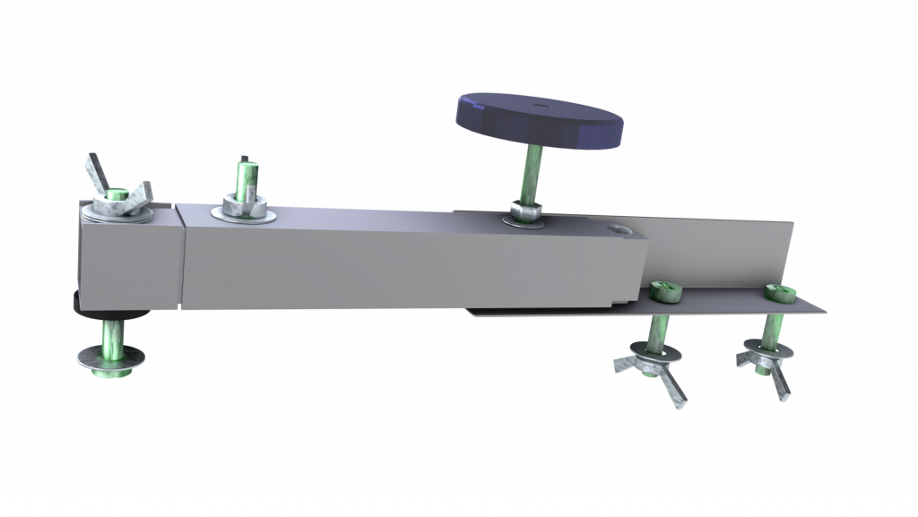
The extender unit is quite complex, consisting of three (or perhaps four including the knob) basic parts. First, we have a mounting bracket which fastens to the horizontal positioning surface. This mounting bracket is fixed, and will be reused for all screens we wish to register, so we only ever need two of them.
The second part is an extendable arm, which may be locked in place for a given length, and the third part is a front connector which provides a mounting point for the screen clamping system.
Materials used
Apart from the typical nuts & bolts, wing nuts and rivets, we will need some other materials which deserve some explanation.
To make our 4mm screw knobs, we will need some 4mm x 50mm screws or bolts, 4mm metal washers, polyester resin, silicone sealer, zip lock bags and corn startch.
Whenever we make a riveted join between two metal sections, we reinforce that join using epoxy glue.
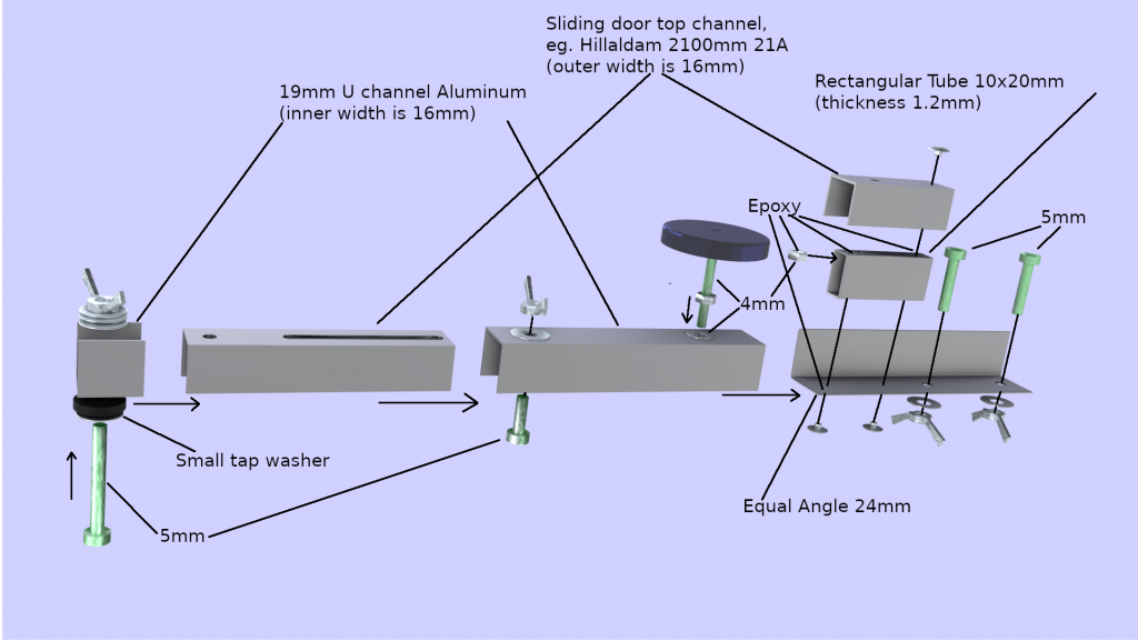
In our previous section, we made some stuts using a 10x20mm rectangular aluminum tubing. We will use the same material here, but a much shorter section.
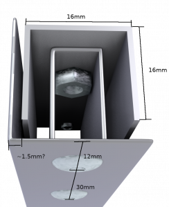
In addition to that, we use a 24mm equal angle aluminum length, and a 19mm U section, obtainable from the same area in the hardware store. Looking at the U section from the end, the 19mm section measures 16mm on the inner edge of the U section, so the thickness is 1.5mm.
The only tricky piece in the extendable arm, is another U section of aluminum which measures 16mm on the outer edge. This means that the two U sections can fit snugly one within the other and slide lengthways. Such a material is used for the top rail of a sliding door. We found Hillaldam 21A to be perfect for this.
Finally, we use a small rubber tap washer to form a friction lock where the arm attaches to the screen clamp.
Building the parts
The 4mm Turning Knob
This part is really hard to buy, and yet ridiculously easy to make. We will need more of this kind of knob later on too, so it’s really worthwhile to DIY.
To make a knob, first find a suitable form to cast. We used a screw lid from an empty acetone bottle which turned out to be exactly the right size.
Having the knob form, first mix corn starch and silicon sealer in a 50% ratio inside a plastic zip lock bag. Knead the mixture until it is fully uniform and malleable. Then cut a corner out of the zip lock bag and squeeze the mixture onto a surface prepared and dusted with corn starch to prevent sticking. Wear gloves (neoprene, not latex).
Place the knob form over the silicon mound, and press it in. Form the silicon around the mold, and allow to set. Once set, remove the form from the mold. The mold can now be used to cast any number of knobs.
To cast, you will need some resin; a polyester resin is perfect, and is very cost effective. Attach a thread to your bolt/screw using masking tape, and hang it from a support, allowing gravity to orient the screw vertically. Place a metal washer around the screw, and position the screw such that the washer is below the surface of the mold, but the head of the screw/bolt does not touch the bottom. Pour resin into the mold and allow to set. When set, remove the knob from the mold.
Thats all there is to making screws with knobs.
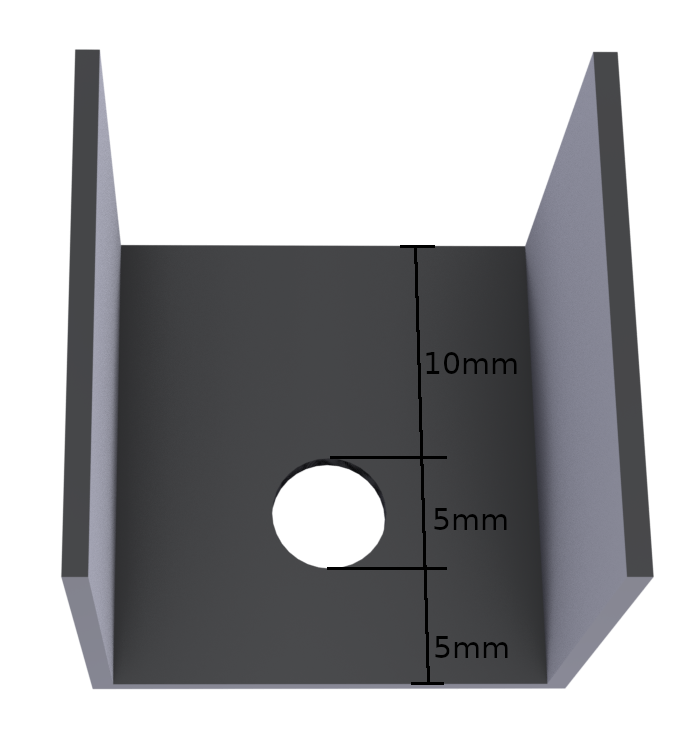
The Fixed Mounting Points
The first part of three, we will need a 120mm long section of 24mm equal angle (90 degrees), a 52mm long section of 16mm wide aluminum (Hillaldam 21A), and a 52mm length of 10x20mm rectangular aluminum tubing.
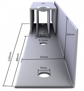
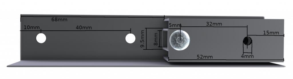
The left mounting point and the right mounting point differ only in the orientation of the 24mm equal angle piece. The 45-52mm section of 10x20mm rectangular tubing is fastened edgeways to the equal angle piece using two rivets and epoxy glue, and the 16mm wide U section is connected to the top of that, again using a rivet and epoxy glue.
A 4mm hole is drilled through the 52x16mm U section and the top of the 10x20mm rectangular portion, 15mm from the front edge, and a nut is glued from inside the rectangular portion, using epoxy glue. It is very important that this nut be held securely in place, as this will be center of the mount point.
Note that the top connection has only a single rivet, and that is positioned as far back as possible. This is because the extension arm will be mounted flush with the top section, and the gap between the edge and the mount point provides a snug fit for the extender section which we will discuss next.
The Extendable Arm
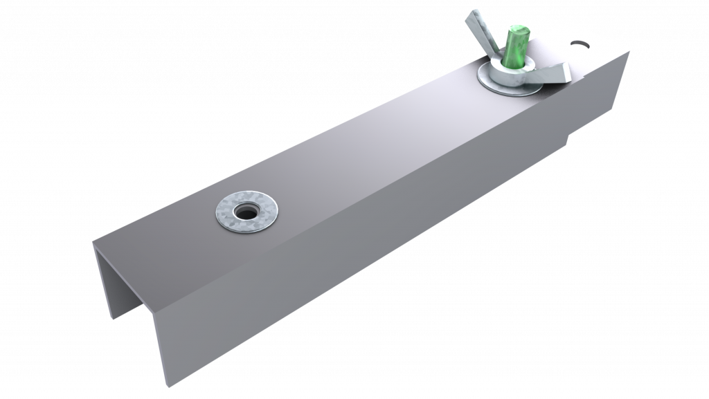
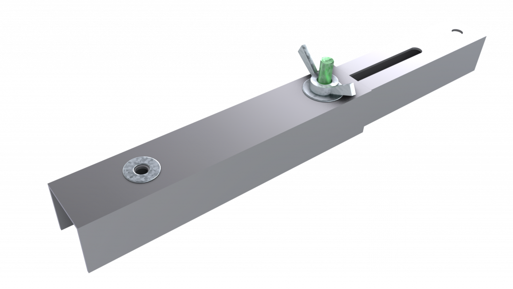
We use a 115mm section of 19mm U tube aluminum (16mm inner), and a 95mm length of the 16mm U section aluminum (Hillaldam 21A), which has a 5x55mm slot cut doen the center of the length, starting 6mm from the edge. On the other end of this piece, we drill a 5mm hole 8mm from the edge.
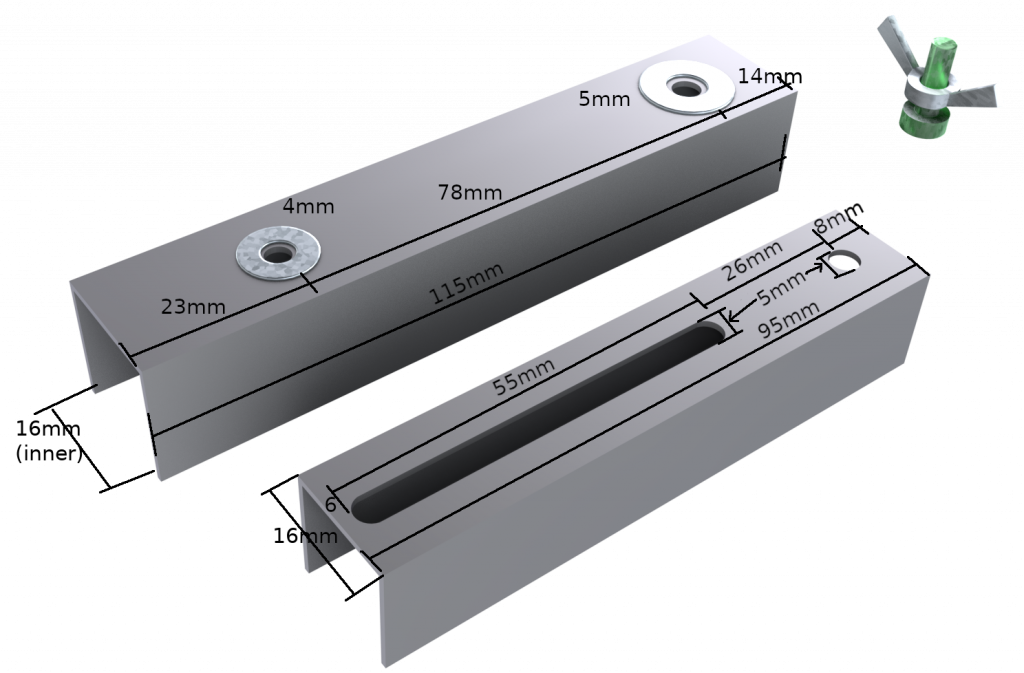
As for the 19mm U tube section, a 4mm hole is drilled 23mm from one end, and a 5mm hole is drilled 5mm from the other edge.
The two sections fit within one another, and are held together by a bolt fed through the slot from below and through the 5mm hole of the top section, and secured with a 5mm washer and wing nut.
The Front Connector
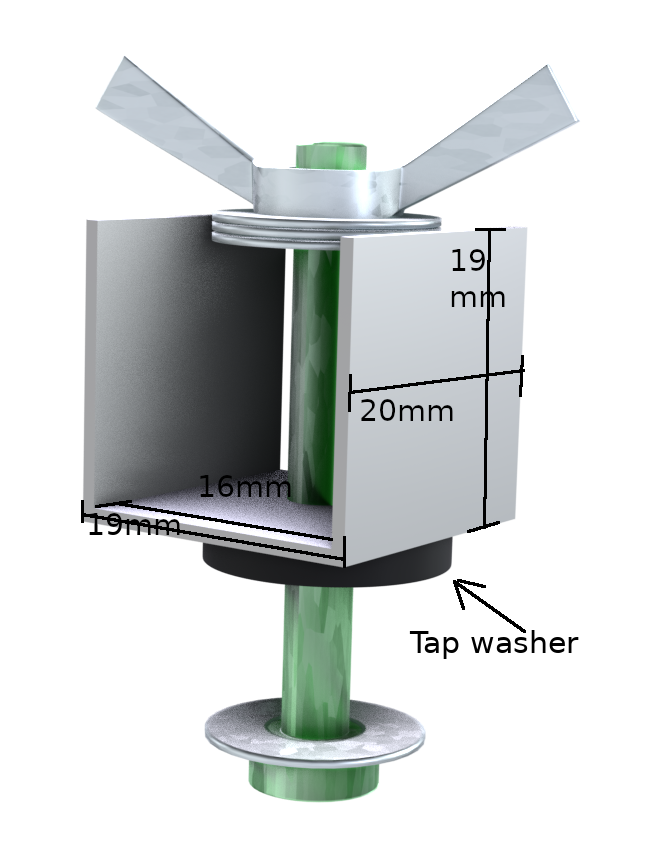
The clamp connector’s purpose is to fasten both left and right horizontal extenders to the screen clamp. This is a very simple component, consisting of a 20mm length of 19mm U aluminum edging, a tap washer, a few 5mm metal washers, a bolt and a wing nut.
This connector is fastened from below the screen clamp, and the tap washer provides a friction lock, partially restricting rotational z-axis movement around the bolt, and completely restricting x/y movement. The 16mm aluminum extender section fits snugly from above, and is tightened using a wing nut.

0 Comments