Building a screen printing press – Part 3
Height Adjustment and Swing Mechanism: Vertical and Lateral Movement
A rather important feature of any versatile screen printing press, is it’s ability to position a screen directly over the target printing area, and also to raise the screen up and away from the target. The size of the target may vary; while the target might be a t-shirt, paper, or other flat object, it may also be something less uniform in size, such as a cap or even a skateboard.
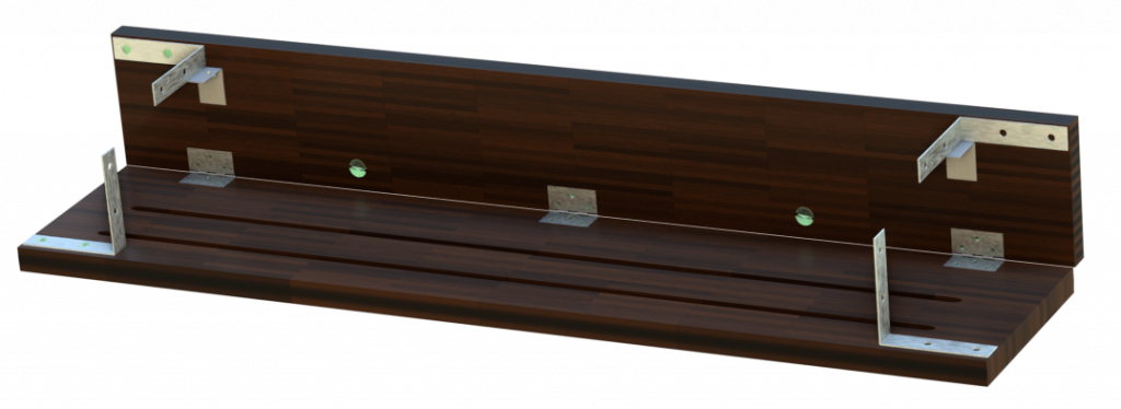
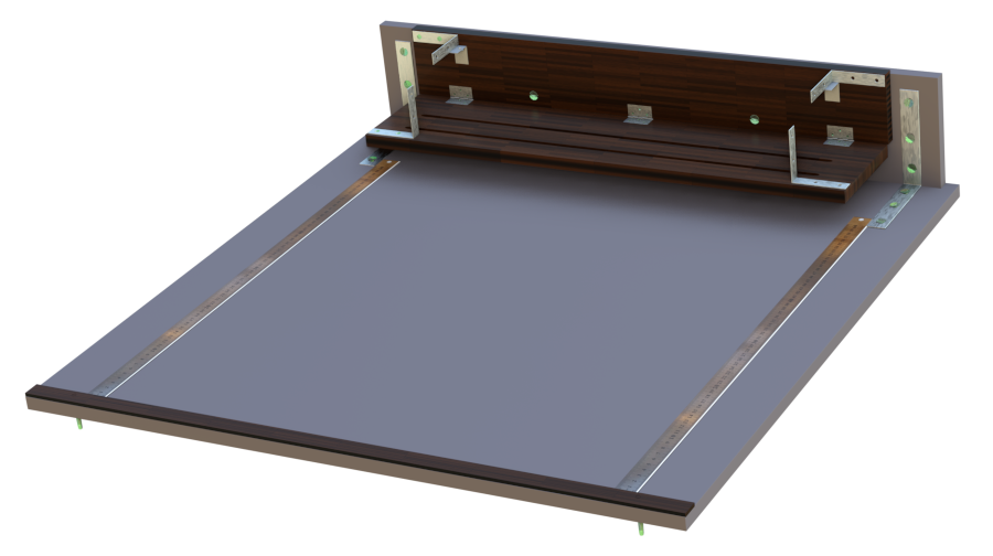
We tackle this problem next, with a simple hinged connection between two planks of wood (Pine wood will do just fine). The vertical section measures 90mm x 645mm x 15mm, and the horizontal section measures 140mm x 645mm x 15mm.
Make sure that the wood sections are dry, straight and according to size, and seal the wood against mosture by using a varnish or lacquer sealer.
The horizontal section have two 5mm slots cut along the length, 35mm and 75mm from the long edge as shown, and 40mm from each of the short edges.
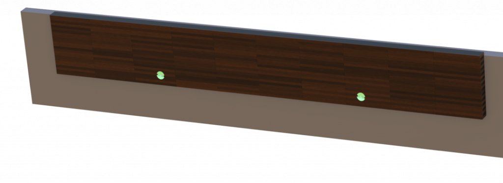
Two 5mm holes are drilled trough the vertical section, 170mm from the short edge, and 15mm from the long edge, to correspond with the slots cut in the back plane.
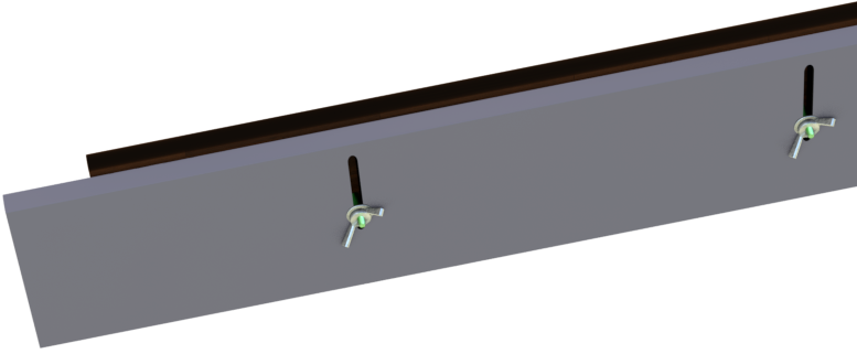
The horizontal section is mounted against the back plane by means of screws, washers and wing nuts, allowing for an adjustable vertical movement.
The middle screw of each of the the outer hinges is 65mm from the short edge, and the middle hinge is, of course, in the center.
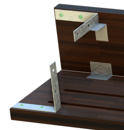
As for the braces, there are four 65x15mm steel braces mounted near the edges (~4mm from long edge) of the horizontal and vertical planks, as shown, and two smaller 25x15mm braces mounted below the upper braces. These braces will be used to connect a screen tensioning device which will allow constrained raising and lowering of the screen.
When done, the whole thing should look like the picture below.

0 Comments